A dual-hop emulation is still a point-to-point emulation, but it supports a middle hop (which could be another location) or a Last Mile scenario at one of the end point locations. In this regard, we can think of dual-hop emulations as multi-link emulations. In this example, we simulate a network link between New York City and Philadelphia.

In this example we use port pair 0 & 1 on the Emulator.
To configure a dual-hop emulation, click Dual-Hop (Single or Dual Link). The dual-hop (single or dual links) configuration screen displays.
Configuring the End Points
First, you must configure the end points (shown with the labels Not Configured Port 0 and Not Configured Port 1 by default).
However, with dual-hop scenarios there is also a middle point (shown as a router icon by default).
Configure the End and Middle Points
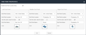
Click either Ethernet port icon to open the End Point Properties panel.
You have two options for configuring end points:
- If you select Enable End Point Location Entry, as you start typing, a list of countries and locations within the country appear that match your criteria. Select the country and the location from the drop-down lists. The latency between the two end point cities is automatically determined.
- If you deselect Enable End Point Location Entry, the latency associated with the distance between the two end points must be entered manually.
You can also change the icons using the Change Icon buttons to better represent the location of the end point, for example, a corporate HQ building.
![]()
Users can add their own icons to the icon database. Click Browse at the top of the end point icon dialog, browse to the image file, then click Upload. The icon is added to the list in the above diagram and remains unless selected and deleted by the user.
Configure both end points. You can now see that the end points have been successfully configured with the locations specified. The end points are looked up and a corresponding latency is determined. When you click OK, a message pops up explaining extra latency of x mS has been added to the scenario as a result of configuring real locations.

You can now see that the end points have been successfully configured with the locations.
Configuring the Links
We now need to configure the links between the end points. In a dual-hop scenario, there must be at least two links.
Click the relevant link. It is advisable, although not required, to configure the links in numerical order. If you don’t want to configure Link 1 and Link 2, these must be disabled. They are enabled (green) by default.
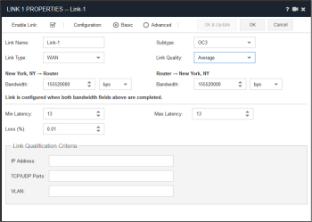
The Link Properties panel is displayed for the relevant link:
Decide if you want to enable the link at this stage.
You can also change the Link Name to something more specific.
Select the Link Type, Subtype and Link Quality that you require.
The Bandwidth, Latency (if you enabled End Point locations in the End Point configuration) and Loss (%) settings are automatically completed for you.
You can overwrite any of the impairment values individually, or you can select Custom from the Link Type to allow manual entry of all impairment values.
Link 1 is now configured and ready for use, but for a dual-hop scenario we must also configure a link associated with the other end point. Therefore, we need to repeat the process for a second link (usually called Link-2). The following example uses updated icons.
Repeat the link configuration process, but not the end point configuration, for each link that needs to be configured.
Cumulative Impairments
The impedance metrics for each link are added together. This means in our example there is a latency of 13mS (which includes 3mS for the end point configuration between New York and Philadelphia, and between 4 and 7mS latency on link-2, which includes 2mS latency between Philadelphia locations. This gives a cumulative total latency of between 17mS and 20mS, and an overall round trip time of between 34mS and 40mS.
Link Qualification Criteria
When you configure multiple links, it is necessary to define criteria specifying what traffic travels over which links. If you don’t do this, everything goes down the first configured and enabled link.
The Link Qualification Criteria can also be used as a traffic filter. For example, if you select a range of IP addresses for a particular link, only traffic associated with these source and destination IP addresses traverses this link.
When no links exist to handle certain traffic, the traffic is dropped by the Emulator.
Specifying what traffic travels over which link is handled in the Link Qualification Criteria section of the Link Properties panel.
The Link Qualification Criteria section allows you to select the IP addresses, TCP/UDP Ports, and the VLAN tags that are allowed to run over this link.
Refer to Link Qualification Criteria Data Values for a detailed description of the input options.
To start the emulation, click Start in the Setup & Control page.
Saving the Configuration
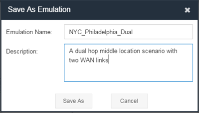
To save the configuration, click Save As at the top of the Setup & Control page.

An emulation name is required. A description of the emulation is optional.
Click Save As to store on the appliance. Emulation configurations are not shareable when saved on the appliance. Users only see their own emulation scenarios from the web GUI.
However, any saved emulation scenarios can be run from the LCD panel.

