Point-to-point emulation simulates one or more network links between two locations or devices. In this example, we simulate a network link between New York City and Philadelphia.
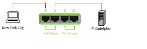
In this example, we use port pair 0 & 1 on the Emulator.
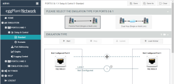
To configure a point-to-point emulation, click Point to Point (Single or Multi Link). The point-to-point configuration screen displays.
Configuring the End Points
Next, we need to configure the end points (shown as Ethernet port icons with labels Not Configured Port 0 and Not Configured Port 1 by default).
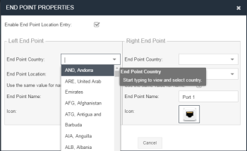
Click either Ethernet port icon to display the End Point Properties panel.
You have two options for configuring end points:
- If you select Enable End Point Location Entry, as you start typing, a list of countries and locations within the country appears that matches your criteria. Select the country and the location from the drop-down lists. The latency between the two end point cities is automatically determined.
- If you deselect Enable End Point Location Entry, the latency associated with the distance between the two end points must be entered manually.
You can also change the icons using the Change Icon buttons to better represent the location of the end point.
![]()
Users can add their own icons to the icon database. Click Browse at the top of the end point icon dialog, browse to the image file, then click Upload. The icon is added to the list in the above diagram and remain unless selected and deleted by the user.
Configure both end points. You can now see that the end points have been successfully configured with the locations specified. The end points are looked up and a corresponding latency is determined. When you click OK, a message pops up explaining extra latency of x mS has been added to the scenario as a result of configuring real locations.

Configuring Links
We now need to configure the link or links between the end points. This is achieved by clicking on the relevant link. It is standard, but not required, to configure the links in numerical order.
When you configure a link, it is enabled (green) by default. If you don’t want to configure the link, either cancel editing it or deselect the Enable Link box. You can configure the link but not enable it if you want to enable it later, for example.
When you click a link, the Link Properties panel (for the relevant link) is displayed in Basic mode (click Advanced to enter Advanced configuration mode).
Decide if you want to enable the link at this stage.
You can also change the Link Name. Then select the Link Type, Subtype, and Link Quality that you require.
The Bandwidth, Latency (if you enabled end point locations in the end point configuration), and Loss (%) settings are automatically completed for you.
You can overwrite any of the impairment values individually. You can also select the Custom from the Link Type menu to allow manual entry of impairment values.
The link is now configured and ready for use.
Repeat the link configuration process, but not the end point configuration, for each link that needs to be configured. Additional links can provide different network experiences for different IPs, VLANs or TCP ports.
To add a link, either click on the + sign for the dotted link at the top or click on the cog on the first link and select Duplicate Link (this copies all the same values set for this link to a second link).
To edit a link, either click on the number of the link you want to change, or click on the cog and select Edit Link.
You can delete a link by clicking on the cog and selecting delete from the menu.
Link Qualification Criteria
When you configure multiple links, it is necessary to define criteria specifying what traffic travels over which links. If you don’t do this, everything goes down the first configured and enabled link.
The Link Qualification Criteria can also be used as a traffic filter. For example, if you select a range of IP addresses for a particular link, only traffic associated with these source and destination IP addresses traverses this link.
When no links exist to handle certain traffic, the traffic is dropped by the Emulator.
Specifying what traffic travels over which link is handled in the Link Qualification Criteria section of the Link Properties panel.
The Link Qualification Criteria section allows you to select the IP addresses, TCP/UDP Ports and the VLAN tags that are allowed to run over this link.
Refer to Link Qualification Criteria Data Values for a detailed description of the input options.
Advanced Mode
The Edit Link Properties dialog in Basic mode allows the user to set up a configuration with point-to-point and dual-hop configurations. Advanced Mode, for the more experienced user, allows for more sophisticated emulation impairment scenarios.
It is sometimes easier to start a configuration in Basic mode, then switch to Advanced mode. In this situation, the following settings would be carried across:
| Advanced Mode | |||
|---|---|---|---|
| Auto-Configuration Mode | Item | Function | Notes |
| Left -> Right Bandwidth | Queue | Link speed and FIFO Queue Bytes | - |
| Right -> Left Bandwidth | Queue | Link speed and FIFO Queue Bytes | - |
| Min and Max Latency | Latency | Random Delay | Values are copied symmetrically to Left -> Right and Right -> Left. |
| Loss (%) | Loss | Random Drop | Value is copied symmetrically to Left -> Right and Right -> Left. |
In Advanced mode, the Edit Link Properties page appears:
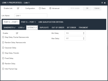
The top line of tabs allows users to configure the properties for the link direction for Port 0 to Port 1, Port 1 to Port 0 and the Link Qualification Criteria. The bottom line of tabs allows users to configure impairments:
- Bandwidth
- Loss
- Latency
- Duplicate
- Out of Order
- Bit Error
- Fragment
A tick mark on a tab means that category of impairment is enabled. With each category of impairment, the user might be offered one or more methods for impairment. For example, for Latency, there are seven options:
In this case, the Random Delay method is selected (which is the same as the Basic mode latency method of impairment). Once the impairments required have been set, click OK to save and return to the Setup & Control page. See the Eggplant Network Standard Impairments List for more information on impairments.
Link Routing (Link Qualification Criteria)
As with Basic mode, when you configure multiple links, it's necessary to define criteria specifying what traffic travels over which links. If you do not define this, everything goes down the first configured and enabled link.
Replacing an Emulation with a Similar Emulation
When you're configuring an emulation, or when you have an emulation loaded, your can replace it with a similar emulation file. Click Load Similar to view a list of emulation files that contain a structurally similar configuration. For example, if the current emulation has one link, then the list of similar emulations will also only have one configured link (even if it is disabled). Equally, if the current emulation has two links, the list of similar emulations will also only have two links even if one or both links are disabled.
Starting the Emulation
To begin the emulation, click Start above the Emulation Configuration display on the Setup & Control page.
In the example above if we connected a PC to Port 0 (New York City) and pinged a server connected to Port 1 (Philadelphia) we would observe the latency of approximately 12mS. This is the round trip latency – the end point location added 3mS to the link quality. For a WAN type OC3 network of excellent quality, the latency would be 3mS, giving a combined total of 6mS between cities. Therefore pinging one end point to the other produces a round trip latency of 12mS.
When Start is clicked, the emulation starts execution, Start is grayed out, and Stop and Update become active. Load Similar changes to Load & Update.
When an emulation is running, it is possible to load a structurally similar emulation and for it to automatically adjust the parameters to the new emulation and for it to continue running from where the previous emulation was running, without stopping and starting the emulation itself. The structure of the two scenarios MUST be the same in order to do this (both scenarios must have a matching number of end points and links, even if one or more of the links in the current or new scenario are disabled). A single or two link emulation can only be replaced by a single or two link scenario, respectively. If a two link emulation is running and the second scenario also has two links but one of them disabled, it is still possible to replace the first emulation with the second scenario. A single link scenario cannot be replaced with another that has two or more links, even if they are all but one are disabled. Likewise, a multiple link scenario (through link qualification criteria) cannot be replaced by a single link scenario file.
Click Load & Update. A dialog pops up with a list of similar scenario files. Select a new scenario file and click Update or Update & Close. If Update is selected, the dialog remains on display and the list of scenario files is refreshed, removing the current running scenario and adding the previous scenario file. If Update & Close is selected, the dialog closes having updated the running scenario.
Saving the Configuration
If you want to save the configuration, for later use, click Save As at the top of the Configuration – Ports 0 and 1 page under Setup & Control.
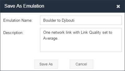
An emulation name is required. A description of the emulation is optional.
Click Save As to store the emulation on the appliance. Emulations saved on the appliance can be used by all appliance emulation users.
